Applicable Industries: Hotels, Building Material Shops, Farms, Printing Shops, Food & Beverage Shops
Gearing Arrangement: Planetary
Output Torque: 60
Input Speed: 3500rpm
Output Speed: Based
Type: PLE90
Voltage: 220V
Application: electric motor speed gearbox
Ratio: 1:3~1:10
PRM: 3500
Packaging Details: box package
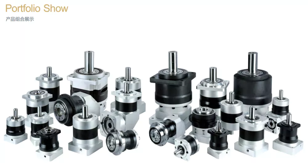
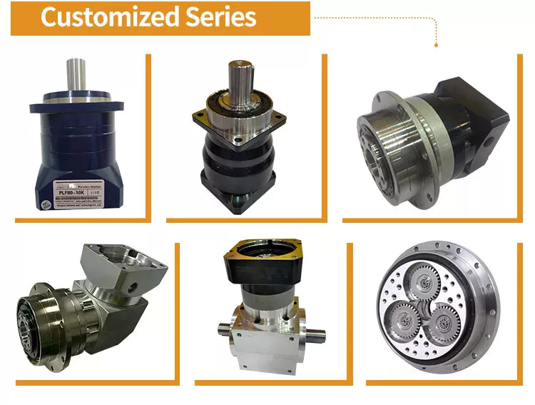
1:3~1:10 PLE90 Series for 90mm flange planetary reducer speed motor gearbox
| stage | single stage 1:3/1:4/1:5/1:7/l:10 | |
| Length (mm) | A | B |
| 55.5 | 154.0 | |
| Rated input speed(rpm) | 3500rpm | |
| Max input speed (rpm) | 6000rpm | |
| Max radial force(N) | 1571 | |
| Max axial force(N) | 850 | |
| No load Turque (Nm) | 0.8 | |
| Full load efficiency(%) | 96% | |
| Return clearance(arcmin) | Precision backlash arcmin <8 | |
Note: Size will according to client’s motor give correct gearbox dimension ..
Packaging & Shipping1. For Europe customers,generanlly send by standard shipping,DHL,Fedex,TNT.
2. Russian customers please tell us your full name,Shipping cost is cheap,generanlly send by CDEK and PONY,less than 20 days delivery,no tax fee and customs chearance easily.
3. Brazil,Argentina,Peru,India customers please give us your tax number after payment.
A Brief Overview of the Spur Gear and the Helical Planetary Gearbox
This article will provide a brief overview of the Spur gear and the helical planetary gearbox. To learn more about the advantages of these gearboxes, read on. Here are a few common uses for planetary gears. A planetary gearbox is used in many vehicles. Its efficiency makes it a popular choice for small engines. Here are three examples. Each has its benefits and drawbacks. Let’s explore each one.
helical planetary gearbox
In terms of price, the CZPT is an entry-level, highly reliable helical planetary gearbox. It is suitable for applications where space, weight, and torque reduction are of high concern. On the other hand, the X-Treme series is suitable for applications requiring high-acceleration, high-axial and radial loads, and high-speed performance. This article will discuss the benefits of each type of planetary gearbox.
A planetary gearbox’s traction-based design is a variation of the stepped-planet design. This variation relies on the compression of the elements of the stepped-planet design. The resulting design avoids restrictive assembly conditions and timing marks. Compared to conventional gearboxes, compound planetary gears have a greater transmission ratio, and they do so with an equal or smaller volume. For example, a 2:1 ratio compound planet would be used with a 50-ton ring gear, and the result would be the same as a 100-ton ring gear, but the planetary disks would be half the diameter.
The Helical planetary gearbox uses three components: an input, an output, and a stationary position. The basic model is highly efficient and transmits 97% of the input power. There are three main types of planetary gearboxes, each focusing on a different performance characteristic. The CZPT basic line is an excellent place to start your research into planetary gearboxes. In addition to its efficiency and versatility, this gearbox has a host of modular features.
The Helical planetary gearbox has multiple advantages. It is versatile, lightweight, and easy to maintain. Its structure combines a sun gear and a planet gear. Its teeth are arranged in a way that they mesh with each other and the sun gear. It can also be used for stationary applications. The sun gear holds the carrier stationary and rotates at the rate of -24/16 and -3/2, depending on the number of teeth on each gear.
A helical planetary gearbox can reduce noise. Its shape is also smaller, reducing the size of the system. The helical gears are generally quieter and run more smoothly. The zero helix-angle gears, in contrast, have smaller sizes and higher torque density. This is a benefit, but the latter also increases the life of the system and is less expensive. So, while the helical planetary gearbox has many advantages, the latter is recommended when space is limited.
The helical gearbox is more efficient than the spur gear, which is limited by its lack of axial load component. The helical gears, on the other hand, generate significant axial forces in the gear mesh. They also exhibit more sliding at the points of tooth contact, adding friction forces. As such, the Helical planetary gearbox is the preferred choice in servo applications. If you’re looking for a gearbox to reduce noise and improve efficiency, Helical planetary gearboxes are the right choice.
The main differences between the two types of planetary gears can be found in the design of the two outer rings. The outer ring is also called the sun gear. The two gears mesh together according to their own axes. The outer ring is the planetary gear’s carrier. Its weight is proportional to the portion of the ring that is stationary. The carrier sets the gaps between the two gears.
Helical gears have angled teeth and are ideal for applications with high loads. They are also extremely durable and can transfer a high load. A typical Helical gearbox has two pairs of teeth, and this ensures smooth transmission. In addition, the increased contact ratio leads to lower fluctuations in mesh stiffness, which means more load capacity. In terms of price, Helical planetary gears are the most affordable gearbox type.
The outer ring gear drives the inner ring gear and surrounding planetary parts. A wheel drive planetary gearbox may have as much as 332,000 N.m. torque. Another common type of planetary gearbox is wheel drive. It is similar to a hub, but the outer ring gear drives the wheels and the sun gear. They are often combined over a housing to maximize size. One-stage Helical gears can be used in bicycles, while a two-stage planetary gear system can handle up to 113,000 N.m. torque.
The design of a helical planetary geartrain is complicated. It must comply with several constraints. These constraints relate to the geometrical relationship of the planetary geartrains. This study of the possible design space of a Helical geartrain uses geometric layouts. The ring gear, sun, and ring gear have no effect on the ratio of the planetary transmission. Nonetheless, helical geartrains are a good choice for many applications.
Spur gear planetary gearbox
The combination of planetary gears and spur gears in a transmission system is called a planetary or spur gearbox. Both the planetary gear and spur gear have their own characteristics and are used in various kinds of vehicles. They work in a similar way, but are built differently. Here are some important differences between the two types of gears. Listed below are some of the most important differences between them:
Helical gears: As opposed to spur gears, helical gears generate significant axial forces in the gear mesh. They also feature greater sliding contact at the point of tooth contact. The helix angle of a gearbox is generally in the range of 15 to 30 degrees. The higher the helix angle, the more axial forces will be transmitted. The axial force in a helical gearbox is greater than that of a spur gear, which is the reason why helical gears are more efficient.
As you can see, the planetary gearhead has many variations and applications. However, you should take care in selecting the number of teeth for your planetary gear system. A five:1 spur gear drive ratio, for example, means that the sun gear needs to complete five revolutions for every output carrier revolution. To achieve this, you’ll want to select a sun gear with 24 teeth, or five mm for each revolution. You’ll need to know the metric units of the planetary gearhead for it to be compatible with different types of machines.
Another important feature of a planetary gearbox is that it doesn’t require all of the spur gears to rotate around the axis of the drive shaft. Instead, the spur gears’ internal teeth are fixed and the drive shaft is in the same direction as the output shaft. If you choose a planetary gearbox with fixed internal teeth, you’ll need to make sure that it has enough lubrication.
The other significant difference between a spur gear and a planetary gearbox is the pitch. A planetary gearbox has a high pitch diameter, while a spur gear has low pitch. A spur gear is able to handle higher torques, but isn’t as efficient. In addition, its higher torque capability is a big drawback. Its efficiency is similar to that of a spur gear, but it is much less noisy.
Another difference between planetary and spur gear motors is their cost. Planetary gear motors tend to be more expensive than spur gear motors. But spur gears are cheaper to produce, as the gears themselves are smaller and simpler. However, planetary gear motors are more efficient and powerful. They can handle lower torque applications. But each gear carries a fixed load, limiting their torque. A spur gear motor also has fewer internal frictions, so it is often suited for lower torque applications.
Another difference between spur gears and planetary gears is their orientation. Single spur gears are not coaxial gearboxes, so they’re not coaxial. On the other hand, a planetary gearbox is coaxial, meaning its input shaft is also coaxial. In addition to this, a planetary gearbox is made of two sets of gear wheels with the same orientation. This gives it the ability to achieve concentricity.
Another difference between spur gears and planetary gears is that a planetary gear has an integer number of teeth. This is important because each gear must mesh with a sun gear or a ring gear. Moreover, each planet must have a corresponding number of teeth. For each planet to mesh with the sun, the teeth must have a certain distance apart from the other. The spacing between planets also matters.
Besides the size, the planetary gear system is also known as epicyclic gearing. A planetary gear system has a sun gear in the center, which serves as the input gear. This gear has at least three driven gears. These gears engage with each other from the inside and form an internal spur gear design. These gear sets are highly durable and able to change ratios. If desired, a planetary gear train can be converted to another ratio, thereby enhancing its efficiency.
Another important difference between a spur gear and a planetary gearbox is the type of teeth. A spur gear has teeth that are parallel to the shaft, while a planetary gear has teeth that are angled. This type of gear is most suitable for low-speed applications, where torque is necessary to move the actuation object. Spur gears also produce noise and can damage gear teeth due to repeated collisions. A spur gear can also slip, preventing torque from reaching the actuation object.